Tuesday, December 06, 2005

Fun Little Project: Minty Mouse


First off - I'll admit - others have used the same name for their projects like this. And no, this really isn't directly related to electronics. But, it is related to fabrication which is usually the last, and most overlooked, step when doing a project. You've got a wonderful little circuit that amplified headphones, charges your iPod, and squeezes fresh orange juice, but how do you package it? Radio Shack sells some nice project enclosures at fairly reasonable prices ($2.29 - $6.99 right now) that give a nice finished look to a project.

You can also use items that aren't necessarily designed for the hobbyist, but which work very well. As in this project, the Altoids and Altoids-like tins are fairly popular for their small size, durability, and cheapness; you also get mints as a bonus! Gladware, Ziploc, and other similar containers are relatively cheap and can provide an assortment of sizes for various projects. They can also be made water-tight fairly easily and are made from thin plastic which is fairly easy to work with. For my Christmas light project this year, I'm building everything into a cheap Stanley tool box that I picked up for around $10 at Lowes.


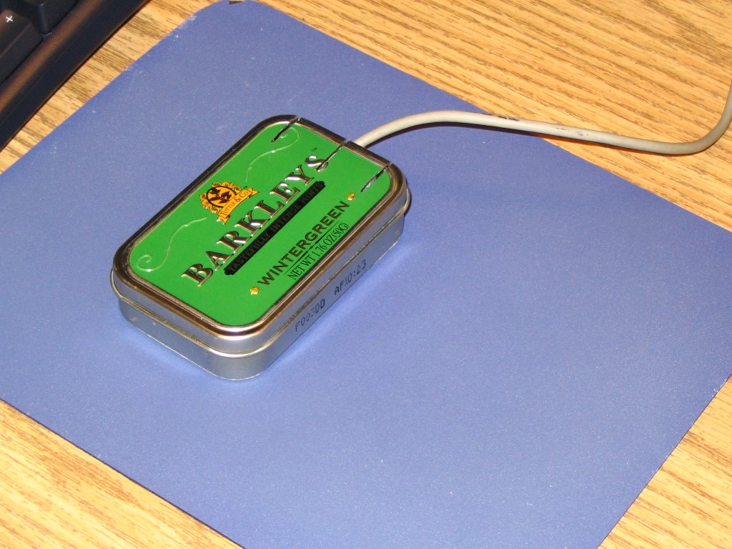
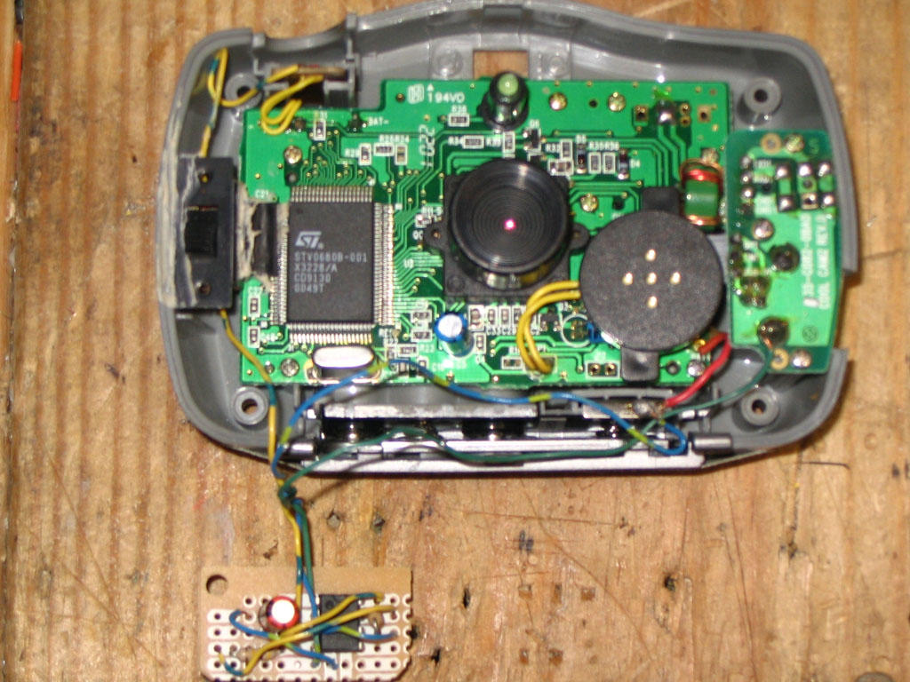
With all of that out of the way, here are the details on the construction of my version of the Minty Mouse. I started with a pseudo-Altoids tin and an old mouse that I found at work. I opened the mouse, discarded the top piece, removed the circuit board, and cut the sides off of the bottom piece to make it slightly smaller than the circuit board. I then sanded what I thought would be the thickness of the tin from the bottom of the bottom piece (later, it would turn out to be too much...) I then drilled a hole through the tin at the location where the mouse ball would need to protrude and smoothed the edges with sandpaper. The circuit board just fit inside the case without wiggle room, but the enclosure for the ball was a touch too tall - sandpaper took care of this and still left everything workable. The buttons were probably the trickiest part of the entire project - both in adding them to the top of the tin and in getting them to interface properly with the switches on the board. I cut three notches in the top of the tin using a Dremel (a tool which I would highly recommend!) with a grinding wheel. I also had to cut a notch out of the top edge of the bottom of the tin so that the buttons would have a place to move downward when they are pressed. Once I had finagled the buttons so that they operated clenaly, I used the trial and error method of determining how far above the switches the bottoms of the buttons were and bent two 'U'-shaped pieces of aluminum which I super-glued to the buttons.

[edit] I forgot to mention what I did to fix the fact that I had sanded too much off of the bottom of the mouse. This fix was accomplished by cover the bottom of the tin with a packing label (also procured from work...) and building up a bar at each end of the bottom with thin strips of labels. The other advantage provided by this is that it makes the bottom look uniform (and covers up the lousy hole that I cut in the tin...) and helps to elevate the ball so that it rolls better. [/edit]

All in all, this was not a terribly difficult project, just time-consuming, but I think the results are neat, and it's always interesting to see the looks on people's faces when the see you mousing with a small tin - especially if you open it up and offer them a stashed mint!

Tuesday, November 22, 2005

Computer Setup

When building electronic projects, it's sometimes nice to have a PC around - for looking up datasheets online, pulling up schematics, or even for providing I/O while testing a circuit. My recommendation for a machine would be to use an older computer with a Pentium II 233 or so processor and as much RAM as you can cram into it. The older machine is nice in that it is fast enough for most simple things that it will be used for on a bench, but old enough that it can support all sorts of old cards and should have most of the "legacy" ports built into it.

These "legacy" (I hate that word - these are such good ports, they're just old - call them classics or something) ports are the standard parallel, serial, and MIDI. The parallel port, which long-time readers of this blog should know is my favorite, provides 12 digital output lines and 5 digital input lines. The serial port is another handy one which provides a TX (transmit) and RX (receive) line which can be used for programming, data-acquisition, and other similar uses. The unsung hero in my opinion of these classics is the MIDI port which provides 4 analog inputs which are each converted to an 8-bit value and 4 digital inputs.

In addition to ensuring that these ports are present, the machine should have a network interface card (NIC) if you are planning to get online, or at the least a modem and a phone line. It might also be wise to look for some of the older ISA cards that are available that provide extra ports and connectivity - check eBay, local auctions, or old computers that people might be willing to part with for these.

For software, I would suggest running either Linux or a version of Windows prior to Windows 2000 - Windows 98se is a good choice as it is the latest version before 2000 that isn't ME (I would advise no one to run ME...). The old versions are suggested because the versions of Windows that are NT based have security to prevent low-level access to the hardware ports. Also - it's nice to run real DOS sometimes for older applications and command-line based programs that you might write. Linux is also a very nice choice since it is so open, easy to program for, and lots of people who do hardware work run it.

Programmable Integrated Circuits

A highly useful component for all sorts of projects is the Microchip brand PIC (programmable integrated circuit). The chips contain a microcontroller, some RAM, and some storage space (quantities and speeds depend on the particular model). Basically - one chip can act as a tiny stand-alone computer with inputs and outputs for controlling other circuits. Most are programmable in-circuit allowing for updates to the code that is run. To program one, you will need to build or buy some sort of PIC programmer (specifics again vary by model of chip to be programmed). You will also need some software for compiling code (unless you want to write assembly - your choice!) and sending it to the PIC. Microchip itself provides a free integrated devolpment kit (IDE) called MPLAB that works very well.

If you are having troubles coming up with uses for this highly versatile devices, there are many ideas and projects out there. Good luck!

Thursday, November 17, 2005

Etching a Circuit Board

You've got a circuit that you've prototyped on a breadboard, built using perfboard, and now you want something a little more professional to sell/give away/use/whatever. Or maybe you don't. Either way - you might want to take the next step with a good circuit and etch your own circuit board. This makes construction easier, the circuit potentially more compact, and it looks a lot nicer to boot. There are a few different ways to go about making the board - the most common is to apply some sort of a mask to a copper-clad board and then soak the board in a solution that dissolves the non-masked copper. Laying out the mask can be done by hand with a resist-ink pen (RadioShack sells a decent kit for doing this), ironing on a printout from a laser printer, or by using a special photo-resist board.

Another method which is somewhat popular (but much more difficult) is to make (or buy) a computer numerically controlled (CNC) mill. This is basically a drill press that has some method of either moving in two dimensions or moving the board in two dimensions that is controlled by a computer. This allows the piece to move past the drill bit, which is controlled vertically by the computer. If the bit is just below the surface of the piece as it is moved, a line will be cut out of the copper cladding. If the piece stops and the drill bit goes down, a hole is drilled through the board where a component will go. This whole setup, while complicated, allows for nearly complete automation of the process and can produce very nice boards.

Thursday, November 10, 2005

Computerized Christmas Lights

Yup, you heard (read?) right... computerized Christmas Lights! Why? Why not?! The last two Christmas seasons I have gone to see a very interesting light display in Winona Lakes that was put together by one of their Computer Science professors. It consists of a lot of strands of christmas lights - some on trees, but most on a large conical "Christmas Tree" that is against his garage. All of the lights are controlled by a computer running Linux and some custom software (actually, custom programming language - the guy is a CS prof...) that controls when the lights are on and off, which allows the tree to change colors and display patterns. All of this is set to music that is broadcast via a small FM transmitter, so you can tune in on your car stereo to hear it.

This got me to thinking about how cool it would be to build my own version, on a much smaller scale at first. I looked around and came across a website that dedicates itself to and calls itself Computer Christmas. The layout leaves a bit to be desired, but there are plenty of circuits and great ideas available. This circuit provided the inspiration for me to begin putting my own together using twelve of this circuit and the twelve output lines of the (wait for it...) parallel port. I've had all of the parts ordered since summer and have just been working on getting around to putting them all together. This is where Monday's post comes into play - the boards that they sell work with the parts I already have, making assembly very very easy.

So - be watching for further updates on this project, and hopefully around Christmas time some pictures/videos of my light display.

Monday, November 07, 2005

Great Site with (sadly) Only One Product

I was researching some equipment for work and came across www.simpleio.com which has an opto-isolated triac board that they sell in various different forms. First - there is a version with eight triacs and another with four. They also sell the same boards without terminal connectors for a substantial saving, kits that can be assembled (with and without terminal connectors), and just the bare boards that can be populated with your own components. As if this weren't enough - they also have the schematics and board layouts available to download for free! But wait, there's more! There's also a section with details about how the circuit and the individual components work. The whole feeling of the site can be summed up quite well in this from the schematic page: "I hope you like this enough to buy the boards (the triac output bare boards are fun!), but even if you don't buy from us, you may know someone who will." This looks to be an excellent site and I plan to purchase some of their boards for my own use - more on that later.

Wednesday, October 26, 2005

Add Another Display to your Computer


Want a way to show a little more information on your computer without taking up any of that precious screen real estate and without shelling out the big bucks for another video card and monitor? A simple (and cheap!) HD44780-based (or compatible) character display can provide all this with a little money and a little effort. Connections are fairly simple - there are eight data inputs to the chips which connect to the eight output lines of (you guessed it...) the PC parallel port. The next bit is a little tricky, depending on your display. Some displays run off of +5 volts which is quite easy to get - it is quite common on computers and is also easy to generate using an LM7805 voltage regulator. Others, like the one that I used, require -5v to run which isn't quite so easy to find or make. I found a handy little circuit that uses the very common and quite useful 555 timer to convert an input between +6v and +35v to -5v.

There is a lot of software out there for sending text to the display - from a Linux kernel driver to a WinAmp plugin to all sorts of programs for displaying system information.

Circuit simulators

A good way to test a circuit design without actually going to the trouble of buying the parts, putting it together on a breadboard, and then trying to troubleshoot it/buy new parts when it (almost inevitably) fails is to use a circuit simulator. One that I've used and like fairly well is a java applet that is simply called "Circuit Simulator". It has quite a few different components that it simulates and since it is java, it should work on any platform that supports java - MacOS, Linux, even Windows.

I've used other simulators, but I can't remember what the names of them are at the moment, but I will check with some of my friends who have used them as well to see if they can remember specifics. Searching at the moment is proving fruitless... more to come later, hopefully...

Tuesday, October 25, 2005

Small, Cheap Digital Camera

While shopping at Wal-Mart the other day, I came across a little digital camera that was advertised as being "keychain-sized". The resolution and number of pictures is equivalent to what the camera I used in this project but it is about an eighth the size and uses only one AAA battery instead of three. Using this for kite-based photography would allow for flights in lower wind speeds. There a couple of issues that I can think of with using this camera instead of the larger one. The first is that the power on-board the camera would only be 1.5v instead of 4.5v, so you would need another source of power for the 555 timer, perhaps two 3v lithium watch batteries. The other concern I would have is that it might be too light and get tossed around more easily in the wind, but I'm sure there's a way that this could be alleviated.

I've looked around on Wal-Mart's website, but I can't find the camera that I saw, but here's a similar one that I found on another site.

Saturday, October 22, 2005

Another Site with Good Circuits

Here's another good site with some interesting circuits and even some board layouts for etching your own (I've yet to post that tutorial - that will be coming soon - promise!). The circuits are categorized into light & LASER, sound & radio, power supply, auto, computer, and phone circuits. There are quite a few that look to be really interesting and useful; I'm considering making the automatic headlight dimmer, for example. Looks to be a good resource for finding intersting circuits to build and he even gives some advice on another page for where to get parts.

Monday, October 17, 2005

Chip Directory - A Handy Resource

Here's a handy resource that I found - a chip directory that lets you search for information about just about any integrated circuit you might come across. This would be very useful for finding out pinouts, looking up manufacturers, or discovering exactly what that weird chip does that a particular circuit calls for. Having played around with it for a little while, it looks to be pretty good if a little weird at times, but all-in-all seems to be a pretty good resource that's worth bookmarking.

Timed Digi-Cam


Here’s a little project that I found a while back when looking for a way to take aerial photographs from a kite. I needed a way to trigger the shutter for the camera for the ground, and had toyed with the idea of some sort of radio-based triggering, but decided to go with a simple timer. The circuit connects to a simple, low-resolution digital camera (which is not the Stylecam mentioned in the article, but similar enough to work) that I got for Christmas a few years ago. I soldered directly on to a few points of the camera - +5, ground, and one side of the push-button that operates the shutter. The heart of the circuit is the classic 555 timer which sends a pulse out roughly once every five seconds that lasts long enough to simulate pressing the push-button. With the capacity of the camera limited to 20 pictures, this lasts for a little over a minute and a half – usually long enough to get the camera and kite up to a decent height for interesting pictures.

Saturday, October 15, 2005

Simple Project: SNES RF-Adapter

Here’s a simple little project that came out of necessity – I had an extra Super Nintendo that I wanted to give to my girlfriend, but none of the accessories for it – controllers, AC adapter, and… an RF-adapter to connect it to a TV. Long story short, I got everything else except the adapter and didn’t want to have to pay big bucks to get a “real” adapter from eBay or used from a used-game place. I decided that it couldn’t be terribly difficult to make, and that this could be an interesting little project.

My first step was to open the existing adapter from my Super to see what makes it tick. It turns out that there really isn’t too much to it, just some circuitry to handle the automatic switching of the signal from the antenna or from the Super. Since this didn’t really work very well to begin with (the picture from the antenna was often fuzzy), I decided to not try to copy this circuit, but instead to use an RF switch I had lying around from a previous cable-TV installation. I soldered and heat-shrunk the cable from an RCA-style plug onto one of the inputs of the switch and left the other side open for connection to an antenna.

That’s it for construction – just a few cables in the right spots and it works like a charm. This just goes to show that not all projects have to be difficult to be useful!

Thursday, October 13, 2005

Live Site Post

"Hidden" Lab on Campus

There are many labs around campus, but I one that often has some empty machines that I don't think is as well-known as say, the one in the basement of Northside Hall or the multitude that are available in Darwin and Wiekamp Hall is the one that is to the left of the circulation desk in Schurz Library. It is sort of tucked away and therefore not as visible as the others, but the signs are there for it. There are about 20 PCs and Macs available, with a printer and some scanners as well. It does get full sometimes, but often times it's not too hard to find a free machine.

Wednesday, October 12, 2005

Wikipedia Topic

I have definitely decided that I will do my Wikipedia topic on my employer, Tenneco Automotive. Right now, I don't know a whole lot about the history of the company, other than it has been around for quite some time. I know that Tenneco owns the brands Monroe, Walker, Clevite, Gillet, Ranch, DynoMax, Fonos, Fric-Rot, Kinetic, Thrush, and DNX. Whew! Also - according to the site, we have "74 manufacturing facilities located in 22 countries and on 6 continents". The company has been publicly traded on the NYSE since November 5, 1999 under the symbol TEN and is a $3.5 billion company with 19,600 employees. I will try to find out some more information about the company on Friday when I can pick the brains of some of the folks who have been around for a little while...

Tuesday, October 11, 2005

Schematics Galore!

Once you have your bench set up check out this site for all sorts of schematics for a variety of different circuits - from Alarms to Video projects and everything in between. Not all of the links work so you'll have to kind of poke around for a good one, but there are usually multiple links to similar projects.

Monday, October 10, 2005

The Well-Stocked Bench (Mark II)

Yesterday I mentioned some of the essentials for a well-stocked electronics bench. Poking around a bit, I've found a nice write-up by Andrew Walmsley and edited by Rod Elliott which goes into a lot more depth than my little post and further discusses how to use some of the equipment they suggest. He also lists some cautions when working with electricity that you would be wise to follow! Definitely worth a look for those considering embarking on this strange and wonderful hobby...

Drive Safely With Your Cell Phone


Or: "Avoid that Crick in the Elbow from Long Conversations While Driving"...

So I realized that when I talk on my cell phone and drive (tsk tsk, I know) I do tend to get a sore elbow after a while, and also I have a tendency to lean with said elbow on the armrest causing me to tilt my head which probably isn't a good driving practice. To top all of this off, if I'm holding the cell phone, that hand is not available to do other things like hold the wheel, adjust mirrors, play with the radio, and... um... eat breakfast. Not that I'd ever do that. So - I thought about this, and have seen some of those gadgets on TV that promise to pipe your cell audio through your stereo via a doofy-looking FM transmitter that plugs into your cigarette lighter. These, in addition to looking doofy, are more than I want to pay for what they provide. I decided that since I already have an adapter to run audio from a headphone jack into my tape deck and since I have a microphone from a headset that I never use that I would make a little plug that would send the audio from the microphone into the cellphone and the output from the cellphone into a headphone jack. To do all of this I stopped at Radio Shack after work and bought a 3/32" stereo plug with solderable contacts and a pair (that's how the packages come... I've now got a spare for another day!) of 1/8" stereo headphone jacks. I then took apart the headset I already had and determined which wires go where with my multimeter. The "sleeve" of the jack (the part closest to the wires) is ground for both the microphone and the speaker. The center goes to the other side of the speaker and the tip goes to the other side of the microphone. I then soldered the microphone to the connections for ground and tip and the headphone socket to the connections for ground and middle. This accomplished, I tried it out by clipping the microphone to my visor and plugging the input to my tape adapter into the headphone jack and dialing a number using voice-dial on the phone. First time - worked like a charm! It's kind of cool really to hear the cell audio going through the car stereo and being able to dial and talk without taking my hands off of the wheel except to answer and press and hold the voice-dial button.

I'll add pictures later - currently on a lousy dial-up connection...
Picture added - I have no macro lens for my camera, so the "in progress" ones look terrible

Sunday, October 09, 2005

Interesting Electronics-Related Site

Surfing around, I found the homepage for "The Under the Pier Show", that is, to quote the site's author "A MAD COLLECTION OF HOME-MADE SLOT MACHINES & SIMULATOR RIDES ON SOUTHWOLD PIER, SUFFOLK, UK". This really is the best description for what all he has built for his venue. The machines are all hand-made and incredibly well-done. The ideas that he has come up with and implemented are very interesting and well thought-out. If you have a few minutes, I would suggest poking around for a while. The site is not the best-organized in the world, and some projects are not available from the main page, but clicking the various links throughout the other descriptions should get to the pages for most of his projects - it's definitely worth looking around!

The Well-Stocked Bench

As a continuation on my previous post about where to buy components, I thought that I would write a piece about what should be on a bench for those looking to start building fun and exciting circuits.

First - equipment. A good multimeter is a must for testing and diagnosing circuits (believe me - this is where a lot of time is spent!). I would suggest getting a digital, autoranging multimeter for the convenience that both offer - digital since it's easy to read and reasonably foolproof and autoranging so that you don't have to worry about what the voltage/amperage levels are before you put the meter on. A multimeter should be able to measure resistance, amperage, continuity, and voltage at the least and some of the better ones can measure capacitance and other useful things. For digital circuits, a logic probe is handy for showing digital levels when testing and can be bought or fairly easily built.
When constructing a circuit, a soldering iron is a must - my current setup is a generic 35-watt pencil type iron with a 15-watt tip from Radio Shack. The mismatch in wattages is intentional - I like the heat output from a 35-watt iron, but I like the fine tip that comes with the lower wattage tips. This is not dangerous to do - the tip is just a piece of pointy metal. I have found that when it comes to solder, a 60/40 lead/tin solder in the smallest diameter you can find is quite good for most applications. Along with the soldering iron, I would suggest getting a desoldering iron. As its name would imply, this is similar to a soldering iron, except that the tip is hollow and connected to a rubber squeeze-bulb to remove solder from a board. This can have dual-applications - one for fixing mistakes and the other for the removal of components from existing circuit boards, which can be a great way to get parts cheap!
Good lighting is a huge help when working on tricky circuits, especially ones with many small components in them. A setup with two standard fluorescent light fixtures spaced a couple of feet apart overhead will help to eliminate shadows and provide clean, even white light to the bench.

For components - the more the merrier, really! A good collection of resistors in various resistances as well as a good stock of film and electrolytic capacitors is almost always useful - there are many times when a circuit will require some odd resistance or capacitance and it's nice to have all of these handy. They are cheap enough to stock up on without breaking the bank and will most likely show up in one form or another in most circuits. LEDs and standard diodes are also good to keep a decent stock of - again they are fairly cheap, and many circuits will use them - LEDs are especially useful for diagnosing digital circuits or for building into them to show logic levels at key points. For the digital enthusiast, a must-have in nearly any circuit is the LM7805 5 volt voltage regulator. This will take input from a power supply ranging from ~6v to ~35v and convert it to 5 volts - the standard logical high level used by most chips. Caution on these - they do tend to get hot when they're running, especially when input is toward the high-end, so you might want to stick a heatsink on it. Common digital ICs will include the 7400 NAND gate, 7402 NOR gate, 7404 hex inverter, 7408 AND gate, 7432 OR gate, 7486 XOR gate, 7474 D flip-flop, and 7486 J-K flip-flop for a good starting point. Datasheets for all of these can be found through this site.

For prototyping circuits, a breadboard is a good way to play around without setting anything into stone (or solder as the case may be...). Once a circuit is tested and working, it can be made more permanent by moving it over to a electroncis perfboard. This is similar to the breadboard in layout, but is made of formica and has copper cladding on the back to solder to. For making a lot of circuits, or for making a nice-looking board, etching is the way to go. More on this in a later post, as there are many ways to do this...

8x16 LED Matrix


Here's a project that I'm dusting off from a couple of years ago - a homemade 8x16 LED matrix. Basically this is a small version of the type of sign often used for displaying messages along the sides of roads, in stores, etc... The resolution is not great and it's not really wide enough to be totally practical, but it is a good proof of concept and an excellent way to hone the 'ol soldering skills.

The device is really quite simple from the hardware point of view - it consists of 128 LEDs that are arranged into a matrix of sixteen columns and eight rows. The cathodes of all of the LEDs in a column are all tied together and are only grounded when the circuit is completed by a transistor. Similarly, the anodes of all of the LEDs in a row are tied together and are only supplied current when completed by a transistor. The transistors grounding the columns receive their signals from a 74LS154 demultiplexer that has four digital inputs and sixteen digital outputs. The signals must first pass through a 4069 hex inverter since the output from the demux is opposite of what we want (selected output is low, others are high which is not what we want). Only one column can be grounded at any given time. The input to the demux comes from four of the output pins of a PC parallel port. The rows are driven using the other eight output lines from the parallel port so that any combination of rows can be high at any one time.

This is it for the hardware - everything else is done in software. For this project I have written the test software in Microsoft QuickBASIC 4.5 but have ported the code to C++ so that it can run well on most architectures. Because only one column is grounded at any given time, I had to rely on persistence-of-vision to make it appear that all columns are lit when needed. This is accomplished by looping through all of the columns very rapidly and setting the output on the rows as necessary when the proper column is grounded. This results in a fairly smooth looking picture without too much flicker. The most common application for this sort of sign was the first program that I wrote for it - displaying a scrolling message. Due to the limits on the width (approximately 2.5 characters) scrolling is required to display all but the shortest messages. The software for this is quite simple - just an array to hold all of the row values (I developed a simple font that converts characters to the correct row values) that gets output to the display. When it comes time to scroll, simply rotate the array so that position 1 of the array corresponds with the first column on the display.

Sourcecode (QB)

Schematic - I cannot find the schematic that I based mine on that I was going to post here, and I haven't yet drawn one for what I built - I'll try to make this link useful soon...

Saturday, October 01, 2005

Put Your Electronics Knowledge to Use: Become a Ham!

Sorry if this sounds a little "sales"ish...

One good way to put electronics knowledge and love to use is to become an amateur radio operator (ham)! This is a very interesting field that allows you to talk to people the world over, assist in emergencies, send pictures, and much much more. This is considerably different from just using a CB radio to talk to people - first, a license from the FCC is required so not just anyone can get on - also, the number of available frequencies and the power allowed on each are consierably greater than anything available without a license.

The best way to get started would be to take some practice tests, read some books, and find a local test time and location. The cost of taking the exam is typically less than $15 and there are only 35 questions, so it shouldn't take more than half an hour.

Monday, September 26, 2005

Good blog: Engadget

Via The Best of Weblog, Inc. again, I found another good blog that is tech related, Engadget. Their biggest feature seems to be delivering news of new products, along with reviews and commentary. Because most of the content is about new items, it does kind of read like an ads site, but the blog entries don't normally read like press releases, so it keeps it feeling fresh instead of like another corporate outlet. All in all, this seems to be a nice site to keep abreast of what's new in the tech world and get a few reviews of what's out there.

Sunday, September 25, 2005

Where to buy Electronic Components

For any good electronics project, you will need components in order to, well, have something to build from. Here are a few of the places that I use and their pros and cons.

My current favorite place is an online store called Digikey that has a tremendous selection of components and a catalog the size of a large phone book. Their prices are reasonable and their shipping is quick – the only caveat on the shipping is that I recently had some trouble with USPS, and was told by the (very helpful) customer service representative that they prefer that people use UPS Ground since it is insured and trackable.

Another place that I occasionally use is Radio Shack. They have a slim selection of (often expensive) parts but are local and good for getting what is needed in a pinch. I would suggest buying bulk packs of resistors and capacitors if only a specific value is needed so that the individual piece is cheaper and so that you have a nice selection of parts for future projects. Believe me, it’s always good to have more parts than you think you’ll ever need – chances are you’ll be working on finishing up a circuit late at night and run into a need for some obscure part.

Another online store that I used to use is Futurlec. I say used to use, because while their prices are great and their selection is quite decent, the shipping time is quite long (often more than a month). This alone wasn’t such a big deal, but their customer service has seemed to have gone downhill in the last couple of years. I’ve had some triacs backordered since August. Of 2004. Service has not been very helpful in getting this resolved even after several attempts. This could, of course, be an isolated incident so you might try them if you want – when I first started using them they were pretty good.

I’ve also heard good things, but never purchased from, another online store - Mouser. Since I’ve never actually used them, I can’t give a recommendation from personal experience, but they sound pretty good. Along this vein, some others that I haven’t tried but that look good are Jameco and Sparkfun which has a nice collection of tutorials to help give some ideas. One advantage to using Sparkfun’s tutorials is that they often have the specific parts you need to do them in their online store. Some advertising!

Give these sites a try, get a good anti-static drawer parts organizer, and flesh out your collection of parts so you can get your projects going in the future. Nothing helps more than having what you actually need so you don’t have to try to hack something together to finish a project when you just don’t want to wait to get the part you need.

Thursday, September 22, 2005

Fun With an RGB LED!


So I bought this RGB LED (Red,Green,Blue Light Emitting Diode) from Digikey, one of the better online electronics suppliers. It comes in a rather interesting package a 6-pin DIP instead of the typical elongated hemisphere normally associated with LEDs. There are three cathodes and three anodes making each LED entirely independent from the other electrically, yet they share a common space physically, allowing for more flexibility electronically but also for good mixing of the colors.

This is all well and good, and a very interesting little piece of electronics, but - what good is it? Well - you may recall that the primary colors of light are Red, Green, and Blue - which, not coincidentally are the colors in this LED. So, by varying the intensity of the three elements of the LED, any visible color can be created. I decided that the best way (or, should I say the easiest...) to accomplish this feat would be to use three of the digital output lines of the parallel port of a PC. This works well for turning each element on and off, but does not allow for different intensities - remember, it's a digital output port. How to accommodate this feature then? Three words: pulse-width modulation (PWM). Basically - you can simulate different intensities by moving the LED from high to low really really fast. This is where we move from the hardware side to the software side.

For software, I just used my old standby for DOS programming, Microsoft QuickBASIC 4.5. Please, hold the laughter if you know about this "language" already - it works fairly well for doing this sort of thing and allows for reasonably rapid testing using the interpreter. This does, however, lead to some speed limitation, as the interpreter and even the compiled output are not terribly fast even on a good machine. Due to this limit, I can only do about 32 different levels per segment for a total of 32x32x32=32,768 different colors. I think that using a different language, such as C++ and inline assembly code I could take this a little higher and provide smoother looking output from the LED - as it is, you can definitely see some blinking going on in the lower intensities from the PWM.

Here's the code for a program that causes the LED to go through a few of the colors it is capable of - the visible spectrum in one intensity:

DECLARE SUB led (r, g, b)
DECLARE SUB lednum (col)

DO
FOR c = 0 TO 96
lednum c
NEXT c
LOOP WHILE INKEY$ = ""

led 0, 0, 0


SUB led (r, g, b)
opt = 0

r2 = 65 - r
g2 = 65 - g
b2 = 65 - b

FOR x = 1 TO 64
IF x MOD r2 = 0 THEN opt = opt + 4
IF x MOD g2 = 0 THEN opt = opt + 2
IF x MOD b2 = 0 THEN opt = opt + 1
OUT &H378, opt
NEXT x
END SUB

SUB lednum (col)
IF col > 0 AND col <= 32 THEN led col, 0, 32 - col
IF col > 32 AND col <= 64 THEN led 63 - col, col - 32, 0
IF col > 64 AND col <= 96 THEN led 0, 96 - col, col - 63
END SUB


The function led takes the Red, Green, and Blue intensities as input and has a (I'm thinking rather inefficient, but haven't messed with it much yet) loop for doing the PWM and sending the output to the first three data lines of the parallel port. The function lednum takes a single color value for input ranging from 1 to 96 (32*3) and converts this number to the RGB value of the color at that point in the visible spectrum (ie: 1 = red, 32 = green, 64 = blue; other number are colors that fall between these). The main module just loops through all of these colors to show a spectrum until the user presses a key on the keyboard.

All-in-all this has been a fun and interesting project - I have learned some about color theory and how to change intensities with digital output. Future plans for this project include possibly using the sound card to convert the input level to a color, reds for loud, purples for soft to make an interesting color display to connect to a stereo, or possibly to use this as a way of expressing real-world data - stock prices, temperature, etc...

Tuesday, September 20, 2005

The Elusive Wikipedia Article

I've been searching for a while for something on Wikipedia about which I could write that hasn't already been written about, but I'm finding this to be quite difficult. This is mostly because there are so many articles already in existence that it is not an easy task to find anything that hasn't been covered, let alone something about which I have knowledge. About the only thing that I have come up with so far is that there is no article about my employer, Tenneco Automotive, so I guess that I could research and write about that, but that doesn't sound like so much fun. Unless I could do so on company time... hmm... My other thought is to find something that is barely covered, but from the sounds of the assignment on W315 Central, I think it needs to be something that doesn't yet exist. Somebody, please correct me if I'm wrong in this assumption, but that seems to be how the last bullet on this assignment reads.

Sunday, September 18, 2005

Classmate's Blog That's Looking Good

Reading around, Ben's blog is starting to look pretty good. He has some posts that show some rather in-depth research and go beyond just his opinion, although those creep in occasionally - I suspect just to lighten things up and keep him from getting too bored with posting. Hmm.... interesting idea that. Anyway - Ben seems to be doing a good job at keeping up with a good posting frequency with at least one new post every couple of days, which keeps the content fresh and gives readers something to look forward to. One minor nitpick that I supose I could make would be to maybe post more than just one short one on days that he posts short, but on the other hand - he has some nice long posts that more thank make up for it.

Saturday, September 17, 2005

Official Announcement: Blog Topic for the Semester+

I think that I have decided on the topic about which I will write this semester, and that is, not surprisingly, the idea of hobby electronics. I think that this will be the main topic, with perhaps a smattering of the other topics mentioned earlier - hobby robotics and the software that goes with them. In addition, I might make the occasional comment on a related topic that is becoming dear to me - amateur ("ham") radio.

I think that this will leave me with plenty of topic to write about for the coming months and should provide a chance to look into some new areas of interests I already have. Also, I think that the focus should be narrow enough that I won't be trying to write over too broad of an area, mostly by sticking to the hobby side of the topics.

With these topics, I will have posts about what other people are doing in these fields as well as some of my own projects and experiences.

Friday, September 16, 2005

Class blog topics

From the discussion in class, I found some of the topics to be particularly interesting and that could be something I could contribute to. One of these is the idea of having a section discussing the technology available to IUSB students and how it can be used to benefit them. As a CS major, I am fairly familiar with much of the technology, but could also perhaps talk to the OIT to find out what sort of "hidden gems" they might be able to suggest. Another idea that was floated around was a picture of the day. Since I enjoy digital photography and have a fairly decent camera, this could be something I could contribute to as well. I think that the picture of the day idea in addition to photos with some blog entries could add some spice to the site and keep it interesting.

I think that in addition to the topics mentioned above and in the chat room, a calendar of events might be a nice addition, even if it isn't a blog entry, but just some extra content for the site. This could be used as a way possibly to tie into some blog entries - if one of the events on the calendar gets covered in an entry. Just a thought.

Tuesday, September 13, 2005

Potential Wikipedia Wikis

While looking around the Wikipedia website, I think that I have found some interesting articles that I could potentially add some content to, and at the very least and am interested in. The first is an article about the programming language that I first learned, and (ashamedly) return to for the occasional project - QuickBASIC.

Another article I found that would be interesting to work with would be the entry for the Association for Computing Machinery. As a member and an officer for the IUSB chapter, this would be a good topic for me to research and write about.

Monday, September 12, 2005

Research Topic: Hobby Electronics

I think that I have decided that I can write a decent amount on the subject of hobby electronics. There aren't many other blogs dedicated to this, so I can kind of fill a niche so to speak. There are, however, plenty of sites with ideas and circuits for the amateur electronics enthusiast. One good example is a nice collection of projects and the like that a man named David Merrill has collected on his site. In addition to writing about projects that other people have done, I can also post some pictures and schematics of different projects that I have done myself which can help to add some content and get some of my ideas out for other people to critique and possibly suggest improvements for. I could also consider using this as a way for other people to submit their projects and circuits to get them on the 'net. Maybe.

Another idea would be to expand from just electronics into robotics somewhat to feature some of the more interesting things going on in that realm. I would still like to keep to just the hobby side of things instead of going into the industrial or commercial applications, except maybe for really cool stuff. This would allow for some more variety in posts and discussions and could help to draw a wider audience. Also - electronics and robotics tie together quite nicely in that for any piece of equipment in a robotics project to be truly functional it needs some pretty interesting electronics to go with it.

Along with these, another possible way for this to expand (this might be getting out of hand, but this is just some free-thought going on here) would be to tie all of the above into my major and feature some of the more interesting and useful software that can be written for electronics to control the robotics. Hat trick! Hmm... I'll have to ponder on this for a while and see what I can come up with, without the whole thing getting completely out of hand and being very difficult to manage. I might also have to start simple this semester, and then maybe build on this after I've got a good foundation going during this semester.

Sunday, September 11, 2005

Another good blog?

While scrounging the web, I ran across a list on hackaday from "The Best of Weblogs, Inc." One of the links that grabbed my eye was to The Digital Photography Weblog. As an amateur digital photographer, this seems to be a very interesting and informative blog. Every day, a digital picture is featured as the picture of the day, and there are different tips for using digital technology and reviews about some of the different equipment available.

All in all, this appears to be a very good blog that I would like to continue reading, as it provides good content and fairly good writing, as well as reviews and sample photographs to get some ideas.

Saturday, September 10, 2005

Classmates' Blogs

Reading around classmatess blogs is interesting and often informative, giving insight into new ideas and ways of looking at things. Keith's blog has some good posts, some long and informative, others short and to the point. He uses links to help point out ideas occasionally, which is a useful thing.

Another blog that seems to be pretty good is David's. He uses pictures quite well to emphasize posts and has longer posts with some potentially interesting ideas for topics on which to blog.

Please don't be offended if I did not mention any particular blog, as all of them seem fairly decent, these are just two that I have chosen to highlight.

Friday, September 09, 2005

Good blog: Round 2!

As a Mac user, I enjoy reading The Unofficial Apple Weblog for the latest news about Apple Computers and Mac hardware and software. The blog is well-written and informative, combining good stories, good writing, and a good amount of humor. On the humor vein, one recent post pokes fun of the new iPod Nano while discussing its release.

All in all, this is a good blog with strong community support and a myriad of new posts all the time, keeping it fresh and interesting. News isn't just limited to new products from Apple, it also covers software updates, open-source, free, and commercial as well as hardware from other manufacturers, which helps keep it from feeling like one big Apple commercial (though, admittedly, it does do a nice job of advertising).

Semi-decent electronics blog

In my quest to find some good electronics blogs upon which to base mine, I stumbled across this blog belonging to a person who goes by the name "philpem". In particular, he has a view set up that filters his posts to just the electronics-related posts. While he doesn't have a lot of posts in the electronics realm and some of them are not of the highest quality, this is one of the few true blogs I have found on this topic. The whole hobby electronics genre doesn't really lend itself to blogging terribly well, but I think that it is definitely worth a stab to try to create on that does pull it off. Who knows, it could work...

Wednesday, September 07, 2005

Very good blog

One blog that I read quite regularly is the nearly infamous Slashdot. It is wildly popular, with many thousands of people reading it daily. The content is composed nearly entirely of links to advances and news items in the tech world. While there are many new posts per day, with an average I would say of about a dozen new entries per day, the bulk of the content on the site comes from the comments from visitors. The comments are interesting in that they can be nested, making reading them more like a web forum than a standard blog.

The emphasis on the community aspect is one of the largest draws, and is especially evident in entries like this one from today, in which someone asks the readers in general for their opinion on a particular topic, in this case about whether the people who find bugs in software should let everybody know, or only the writer of the software. This allows for many people to voice their opinion on the topic, and opens up new ways of thinking about the idea.

As an example, I would definitely say the Slashdot is a blog that has done it right, and continues to be strong.

Good blog in the hobby electronics realm

Searching around, I found the blog for a really intersting magazine called "Make:". This magazine focuses on interesting ways to use everyday objects to do interesting things, with some focus on electronic circuits that are reasonably easy for the hobbyists to make themselves. I found one project linked from one of the blog posts to be particularly interesting as it combines some of my favorite things into one, those being old computer equipment, electronics, and an interesting way to do something. In this example, a sound card that could not possibly be used with a modern computer as it is is given new life via a simple circuit and some clever programming.

This blog provides a good way to find some new and fun projects that would be good to write about and better to actually play around with.

Sunday, September 04, 2005

Hackaday

A topic that I would really like to write about is hobby electronics. I have always enjoyed meddling with small components to create interesting devices, and would like to learn more about different and interesting circuits and ideas that other people have. One of my favorite blogs for information along these lines is called hackaday.com. While the name might conjure the idea that this is a site for people who break into computers, this is nowhere near the truth. The term "hacker" has a very negative conotation to most people, due to its common misuse. "Hackers" are people who find new uses for existing hardware and software, while "crackers" are the folks who attempt to get into computer systems, often but not always with the intent to cause damage.

This, however, is completely beside the point.

Hackaday, as its name implies, presents a new "hack" every day and allows people to comment on this hack. As such, it is a fairly active blog and gets many comments per day. The topics range from electronics (my strongest interest) to mods (redesigning existing hardware) to software hacks that allow more to be done with less.

Thursday, September 01, 2005

What good are blogs?

I recently came across this blog entry on Will Richardson's site. He describes a small aspect of why blogs are important - that being that they help to bring information to the public and to prevent "ownership" of said data. I feel this is a very good way to look at the subject, and a good reason for them to exist.

Many changes in history have come from the change in the availability of data - from the printing press making literature available to the masses, to information becoming freely available via the internet.

Therefore, I would say that a good blog is one that has value and can be used in the future to help other people. Many blogs can be useful for the opinions expressed about certain events in history, without being pure fact.

My first post on Blogger

This is my first post here. Yay!

-42-