Sunday, March 23, 2014

Printrbot Simple Build Volume Upgrades

I received a Printrbot Simple (late 2013 version) as a (wonderful!) Christmas gift this year. Everything assembled nicely and the prints have been great so far. One thing that's bugged me since day one, however, is the very small build area (roughly 4" cubed). I set out to change that and have decided to detail my process so far and post updates as I continue.

First Upgrade

The first upgrade I did was to print out Thingiverse part number 215294 to increase the build volume from 100mm on the X-axis to 160mm. This was a huge step forward as it greatly increased the number of useful object I could print. It was a relatively simple print (everything was oriented to print on the stock bed) and only required a few parts to be purchased. These parts were:

  • 8mm smooth rod (McMaster-Carr part# 88625K67 or on Amazon)
  • 608 skate bearings (McMaster-Carr part# 5972K222 or on Amazon)
  • Printrbot GT2 Kit (From Printrbot)
  • Miscellaneous M3 screws (Hardware store, McMaster-Carr, Amazon, etc.)


I followed the instructions from the Thingiverse listing and everything went quite well. I cut the 36" rod that I bought in half and only used a small portion of these with the original bed. I used this setup for a couple of weeks before starting to get the itch to grow the printer further. 

A few notes of caution: this build isn't for the feint of heart - it involves dismantling most of the bottom of the printer since the motor plate has to be replaced with a printed piece. Also, don't make the mistake I did and let the nut fall out for the top screw on the left side. It took me quite some time to wiggle that guy back into the right place using a magnetized screwdriver, a steady hand and many attempts. Also, make sure you clean the extra plastic off of the protuberance that hits the X-axis limit switch. I didn't do this at first and was greeted with a very sickening (although not damaging) noise as some of the layers separated.

Second Upgrade

The second upgrade I did was Thingiverse part number 257841 which is a beefier version of the first, but without the adjustable piece that would allow usage of the original bed. If I were to start over from the beginning, i would print just that piece from the previous build and the rest of this build. That would allow the better end-pieces with the adjustable nature of the original. Live and learn! Since I didn't do the adjustable piece and I had planned from the beginning to make a super-big bed, I replaced the stock bed with a piece of Lexan that I cut with a jigsaw and drilled for the screws. I would definitely thing about having this laser cut if that's an option and am considering getting a second piece and having that done. The result would be a lot cleaner and more precise, but this is working for now on the cheap. I've been printing directly on the Lexan, which produces nice shiny first layers and the adhesion has been quite good.

I changed the way the timing belt is attached by using one tension block on each end instead of just on one. I also used Thingiverse part number 275874 to wedge into the opening on the tension blocks so that I could use the timing belt without cutting the belt. This has worked great for giving extra control over the tension and to prevent having to modify the belt in case I ever decide to go "just a little bit bigger"


The keen-eyed reader will notice that the bed is quite a bigger along the Y-axis than it would need to be for the standard Y carriage and the keen reader would be right! This is all the farther I've gotten so far, but there will be more to come (one piece of the next upgrade is on the printer as I type this).

Monday, October 29, 2012

Robot Halloween Costume

I decided it might be time to revive my old electronics blog.

My wife and I built this robot costume for our four year old son this year.


The main part is made from a diaper box spray-painted silver with a detachable front 'control panel'. The hat is made from a wipes box with a plastic fire hat modified to allow visibility out of the hand hole in the box. With 18mo old twins, we have lots of nice cardboard boxes from baby products around our house that make fantastic building and storage products. Leftover foil tape from some duct work helps complete the look and holds everything together.

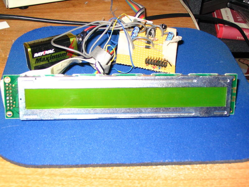
All of the electronics are driven by an Arduino Diecemila. I salvaged a slick little VFD from some scrap equipment - it's a Noritake GU112X16G-7000 (details) and is driven via the serial interface at 38400 baud. Since the Arduino serial levels are inverted from RS232, I had to build an inverting board based on a design I found online. The LEDs at the bottom are 10mm RGB and are driven by a pair of daisy-chained 74HC595 shift registers to save i/o pins on the Arduino. This makes it very easy to add lots of LEDs to a project without a lot of hassle and are quite expandable without a lot of effort. Normally the LEDs cycle through a shifting spectrum with a narrow 'window' to show a nice range of colors at all times. The buttons are arcade style buttons sourced from Sparkfun; they temporarily switch all the LEDs to whatever color is pressed, singularly or mixed to match whatever buttons are pressed (red, green, blue, yellow, cyan, magenta, or white). A small piezo speaker beeps out random 'robot noises' to add another dimension to the costume. I have an ultra bright 10mm red LED in the ball on top (hollowed out Styrofoam) that blinks out 'HALLOWEEN' in morse code. I outlined the front in green EL wire with a commercial EL driver that lets it stay solid, blink slowly or blink quickly; quickly looks the best in my opinion.

On the software side of things, the 'loop' portion of the Arduino code checks the current millis() and performs a modulo to see if it's time to run the various portions of the code (changing the image on the display, checking the buttons, cycling the colors on the LEDs, blinking the red LED, and pushing sound to the speaker). This allows for all of the components to update without blocking so everything runs smoothly. I'm sure there's a better way to accomplish this, but for a quick (ha!) Halloween hack, this seems to be working pretty well. Once I get the code cleaned up a little bit, I'll post it and link it here.

Videos:

(I apologize for the vertical orientation - it worked well for the vertical orientation of the costume and I originally shot them to share on my phone)

Early test - no sound - closeups on the VFD to show the images.
Further along - this time with the sound effects working (still no paint).

Thursday, March 16, 2006

Alphanumeric LED Display


Alphanumeric LED Display
Originally uploaded by DanWake.
HPDL-1414 Alphanumeric Display

I recently acquired a little gem from an old piece of equipment we were throwing away at work - that gem is the HPDL-1414 four character alphanumeric display. It is a small chip manufactured by Hewlett Packard that contains four tiny, red LED alphanumeric displays behind glass magnifying lenses. The chip itself is CMOS, however it runs at TTL voltages, making it easy to interface with. Interfacing is very simple from a logic level as well - simply set the write enable pin high (disable writing), set the 2 bit character address via the address lines, set the 7 bit ASCII value of the character via the data lines, pull the write pin low (enable write), rinse, lather, and repeat for each character. The only disadvantages that I have seen with this display are that it does not support full ASCII (capital letters and some symbols only), the characters are not very bright (although this could be because I'm not giving enough voltage to VDD (I'm currently running it off of the 5v from the parallel port to save wires), and the letters themselves are fairly tiny. Otherwise, this is a great little display that is very easy to work with and tons of fun to write software for.

Currently I have a few functions written in C to put characters at individual addresses, scroll a text string at arbitrary speed (from super, mind-numbingly fast, to as slow as you want), and just for fun a function that switches all of the segments from '1' to '/' to '-' to '\' fairly fast, producing a rather interesting and attention-grabbing spinner effect.

The physical aspects of the construction were fairly straight-forward: I hacked up an old parallel printer cable for the computer connection by using trial and error with a multimeter to find which wire goes to which pin; the case is, fairly obviously, an old Altoids tin which I Dremelled out to make a window and lined with electrical tape. I initially tried to make my parallel cable using a 25-pin header that I tried soldering phone cable to. I would not advise trying this, as phone cable insulation tends to melt at fairly low temperature making it very not-fun to solder. And - after I eventually did get all the little wires soldered at each end, one of my lines was goofed up preventing all of the characters from appearing, and generally frustrating me to the point where hacking up an old printer cable was rather cathartic. Just a word of warning.

So - if you can get your hands on one of these, by all means go for it - I'm sure that it would be very useful in any project for which you can spare a few data lines and want to add a really neat retro looking display to get some data to the user.

Tuesday, December 06, 2005

Fun Little Project: Minty Mouse


First off - I'll admit - others have used the same name for their projects like this. And no, this really isn't directly related to electronics. But, it is related to fabrication which is usually the last, and most overlooked, step when doing a project. You've got a wonderful little circuit that amplified headphones, charges your iPod, and squeezes fresh orange juice, but how do you package it? Radio Shack sells some nice project enclosures at fairly reasonable prices ($2.29 - $6.99 right now) that give a nice finished look to a project.

You can also use items that aren't necessarily designed for the hobbyist, but which work very well. As in this project, the Altoids and Altoids-like tins are fairly popular for their small size, durability, and cheapness; you also get mints as a bonus! Gladware, Ziploc, and other similar containers are relatively cheap and can provide an assortment of sizes for various projects. They can also be made water-tight fairly easily and are made from thin plastic which is fairly easy to work with. For my Christmas light project this year, I'm building everything into a cheap Stanley tool box that I picked up for around $10 at Lowes.


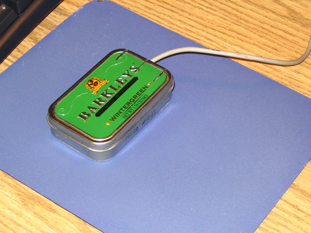
With all of that out of the way, here are the details on the construction of my version of the Minty Mouse. I started with a pseudo-Altoids tin and an old mouse that I found at work. I opened the mouse, discarded the top piece, removed the circuit board, and cut the sides off of the bottom piece to make it slightly smaller than the circuit board. I then sanded what I thought would be the thickness of the tin from the bottom of the bottom piece (later, it would turn out to be too much...) I then drilled a hole through the tin at the location where the mouse ball would need to protrude and smoothed the edges with sandpaper. The circuit board just fit inside the case without wiggle room, but the enclosure for the ball was a touch too tall - sandpaper took care of this and still left everything workable. The buttons were probably the trickiest part of the entire project - both in adding them to the top of the tin and in getting them to interface properly with the switches on the board. I cut three notches in the top of the tin using a Dremel (a tool which I would highly recommend!) with a grinding wheel. I also had to cut a notch out of the top edge of the bottom of the tin so that the buttons would have a place to move downward when they are pressed. Once I had finagled the buttons so that they operated clenaly, I used the trial and error method of determining how far above the switches the bottoms of the buttons were and bent two 'U'-shaped pieces of aluminum which I super-glued to the buttons.

[edit] I forgot to mention what I did to fix the fact that I had sanded too much off of the bottom of the mouse. This fix was accomplished by cover the bottom of the tin with a packing label (also procured from work...) and building up a bar at each end of the bottom with thin strips of labels. The other advantage provided by this is that it makes the bottom look uniform (and covers up the lousy hole that I cut in the tin...) and helps to elevate the ball so that it rolls better. [/edit]

All in all, this was not a terribly difficult project, just time-consuming, but I think the results are neat, and it's always interesting to see the looks on people's faces when the see you mousing with a small tin - especially if you open it up and offer them a stashed mint!

Tuesday, November 22, 2005

Computer Setup

When building electronic projects, it's sometimes nice to have a PC around - for looking up datasheets online, pulling up schematics, or even for providing I/O while testing a circuit. My recommendation for a machine would be to use an older computer with a Pentium II 233 or so processor and as much RAM as you can cram into it. The older machine is nice in that it is fast enough for most simple things that it will be used for on a bench, but old enough that it can support all sorts of old cards and should have most of the "legacy" ports built into it.

These "legacy" (I hate that word - these are such good ports, they're just old - call them classics or something) ports are the standard parallel, serial, and MIDI. The parallel port, which long-time readers of this blog should know is my favorite, provides 12 digital output lines and 5 digital input lines. The serial port is another handy one which provides a TX (transmit) and RX (receive) line which can be used for programming, data-acquisition, and other similar uses. The unsung hero in my opinion of these classics is the MIDI port which provides 4 analog inputs which are each converted to an 8-bit value and 4 digital inputs.

In addition to ensuring that these ports are present, the machine should have a network interface card (NIC) if you are planning to get online, or at the least a modem and a phone line. It might also be wise to look for some of the older ISA cards that are available that provide extra ports and connectivity - check eBay, local auctions, or old computers that people might be willing to part with for these.

For software, I would suggest running either Linux or a version of Windows prior to Windows 2000 - Windows 98se is a good choice as it is the latest version before 2000 that isn't ME (I would advise no one to run ME...). The old versions are suggested because the versions of Windows that are NT based have security to prevent low-level access to the hardware ports. Also - it's nice to run real DOS sometimes for older applications and command-line based programs that you might write. Linux is also a very nice choice since it is so open, easy to program for, and lots of people who do hardware work run it.

Programmable Integrated Circuits

A highly useful component for all sorts of projects is the Microchip brand PIC (programmable integrated circuit). The chips contain a microcontroller, some RAM, and some storage space (quantities and speeds depend on the particular model). Basically - one chip can act as a tiny stand-alone computer with inputs and outputs for controlling other circuits. Most are programmable in-circuit allowing for updates to the code that is run. To program one, you will need to build or buy some sort of PIC programmer (specifics again vary by model of chip to be programmed). You will also need some software for compiling code (unless you want to write assembly - your choice!) and sending it to the PIC. Microchip itself provides a free integrated devolpment kit (IDE) called MPLAB that works very well.

If you are having troubles coming up with uses for this highly versatile devices, there are many ideas and projects out there. Good luck!

Thursday, November 17, 2005

Etching a Circuit Board

You've got a circuit that you've prototyped on a breadboard, built using perfboard, and now you want something a little more professional to sell/give away/use/whatever. Or maybe you don't. Either way - you might want to take the next step with a good circuit and etch your own circuit board. This makes construction easier, the circuit potentially more compact, and it looks a lot nicer to boot. There are a few different ways to go about making the board - the most common is to apply some sort of a mask to a copper-clad board and then soak the board in a solution that dissolves the non-masked copper. Laying out the mask can be done by hand with a resist-ink pen (RadioShack sells a decent kit for doing this), ironing on a printout from a laser printer, or by using a special photo-resist board.

Another method which is somewhat popular (but much more difficult) is to make (or buy) a computer numerically controlled (CNC) mill. This is basically a drill press that has some method of either moving in two dimensions or moving the board in two dimensions that is controlled by a computer. This allows the piece to move past the drill bit, which is controlled vertically by the computer. If the bit is just below the surface of the piece as it is moved, a line will be cut out of the copper cladding. If the piece stops and the drill bit goes down, a hole is drilled through the board where a component will go. This whole setup, while complicated, allows for nearly complete automation of the process and can produce very nice boards.

Thursday, November 10, 2005

Computerized Christmas Lights

Yup, you heard (read?) right... computerized Christmas Lights! Why? Why not?! The last two Christmas seasons I have gone to see a very interesting light display in Winona Lakes that was put together by one of their Computer Science professors. It consists of a lot of strands of christmas lights - some on trees, but most on a large conical "Christmas Tree" that is against his garage. All of the lights are controlled by a computer running Linux and some custom software (actually, custom programming language - the guy is a CS prof...) that controls when the lights are on and off, which allows the tree to change colors and display patterns. All of this is set to music that is broadcast via a small FM transmitter, so you can tune in on your car stereo to hear it.

This got me to thinking about how cool it would be to build my own version, on a much smaller scale at first. I looked around and came across a website that dedicates itself to and calls itself Computer Christmas. The layout leaves a bit to be desired, but there are plenty of circuits and great ideas available. This circuit provided the inspiration for me to begin putting my own together using twelve of this circuit and the twelve output lines of the (wait for it...) parallel port. I've had all of the parts ordered since summer and have just been working on getting around to putting them all together. This is where Monday's post comes into play - the boards that they sell work with the parts I already have, making assembly very very easy.

So - be watching for further updates on this project, and hopefully around Christmas time some pictures/videos of my light display.

Monday, November 07, 2005

Great Site with (sadly) Only One Product

I was researching some equipment for work and came across www.simpleio.com which has an opto-isolated triac board that they sell in various different forms. First - there is a version with eight triacs and another with four. They also sell the same boards without terminal connectors for a substantial saving, kits that can be assembled (with and without terminal connectors), and just the bare boards that can be populated with your own components. As if this weren't enough - they also have the schematics and board layouts available to download for free! But wait, there's more! There's also a section with details about how the circuit and the individual components work. The whole feeling of the site can be summed up quite well in this from the schematic page: "I hope you like this enough to buy the boards (the triac output bare boards are fun!), but even if you don't buy from us, you may know someone who will." This looks to be an excellent site and I plan to purchase some of their boards for my own use - more on that later.

Wednesday, October 26, 2005

Add Another Display to your Computer


Want a way to show a little more information on your computer without taking up any of that precious screen real estate and without shelling out the big bucks for another video card and monitor? A simple (and cheap!) HD44780-based (or compatible) character display can provide all this with a little money and a little effort. Connections are fairly simple - there are eight data inputs to the chips which connect to the eight output lines of (you guessed it...) the PC parallel port. The next bit is a little tricky, depending on your display. Some displays run off of +5 volts which is quite easy to get - it is quite common on computers and is also easy to generate using an LM7805 voltage regulator. Others, like the one that I used, require -5v to run which isn't quite so easy to find or make. I found a handy little circuit that uses the very common and quite useful 555 timer to convert an input between +6v and +35v to -5v.

There is a lot of software out there for sending text to the display - from a Linux kernel driver to a WinAmp plugin to all sorts of programs for displaying system information.

Circuit simulators

A good way to test a circuit design without actually going to the trouble of buying the parts, putting it together on a breadboard, and then trying to troubleshoot it/buy new parts when it (almost inevitably) fails is to use a circuit simulator. One that I've used and like fairly well is a java applet that is simply called "Circuit Simulator". It has quite a few different components that it simulates and since it is java, it should work on any platform that supports java - MacOS, Linux, even Windows.

I've used other simulators, but I can't remember what the names of them are at the moment, but I will check with some of my friends who have used them as well to see if they can remember specifics. Searching at the moment is proving fruitless... more to come later, hopefully...

Tuesday, October 25, 2005

Small, Cheap Digital Camera

While shopping at Wal-Mart the other day, I came across a little digital camera that was advertised as being "keychain-sized". The resolution and number of pictures is equivalent to what the camera I used in this project but it is about an eighth the size and uses only one AAA battery instead of three. Using this for kite-based photography would allow for flights in lower wind speeds. There a couple of issues that I can think of with using this camera instead of the larger one. The first is that the power on-board the camera would only be 1.5v instead of 4.5v, so you would need another source of power for the 555 timer, perhaps two 3v lithium watch batteries. The other concern I would have is that it might be too light and get tossed around more easily in the wind, but I'm sure there's a way that this could be alleviated.

I've looked around on Wal-Mart's website, but I can't find the camera that I saw, but here's a similar one that I found on another site.

Saturday, October 22, 2005

Another Site with Good Circuits

Here's another good site with some interesting circuits and even some board layouts for etching your own (I've yet to post that tutorial - that will be coming soon - promise!). The circuits are categorized into light & LASER, sound & radio, power supply, auto, computer, and phone circuits. There are quite a few that look to be really interesting and useful; I'm considering making the automatic headlight dimmer, for example. Looks to be a good resource for finding intersting circuits to build and he even gives some advice on another page for where to get parts.

Monday, October 17, 2005

Chip Directory - A Handy Resource

Here's a handy resource that I found - a chip directory that lets you search for information about just about any integrated circuit you might come across. This would be very useful for finding out pinouts, looking up manufacturers, or discovering exactly what that weird chip does that a particular circuit calls for. Having played around with it for a little while, it looks to be pretty good if a little weird at times, but all-in-all seems to be a pretty good resource that's worth bookmarking.

Timed Digi-Cam


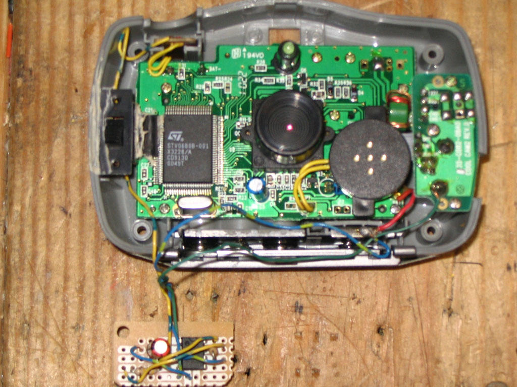
Here’s a little project that I found a while back when looking for a way to take aerial photographs from a kite. I needed a way to trigger the shutter for the camera for the ground, and had toyed with the idea of some sort of radio-based triggering, but decided to go with a simple timer. The circuit connects to a simple, low-resolution digital camera (which is not the Stylecam mentioned in the article, but similar enough to work) that I got for Christmas a few years ago. I soldered directly on to a few points of the camera - +5, ground, and one side of the push-button that operates the shutter. The heart of the circuit is the classic 555 timer which sends a pulse out roughly once every five seconds that lasts long enough to simulate pressing the push-button. With the capacity of the camera limited to 20 pictures, this lasts for a little over a minute and a half – usually long enough to get the camera and kite up to a decent height for interesting pictures.

Saturday, October 15, 2005

Simple Project: SNES RF-Adapter

Here’s a simple little project that came out of necessity – I had an extra Super Nintendo that I wanted to give to my girlfriend, but none of the accessories for it – controllers, AC adapter, and… an RF-adapter to connect it to a TV. Long story short, I got everything else except the adapter and didn’t want to have to pay big bucks to get a “real” adapter from eBay or used from a used-game place. I decided that it couldn’t be terribly difficult to make, and that this could be an interesting little project.

My first step was to open the existing adapter from my Super to see what makes it tick. It turns out that there really isn’t too much to it, just some circuitry to handle the automatic switching of the signal from the antenna or from the Super. Since this didn’t really work very well to begin with (the picture from the antenna was often fuzzy), I decided to not try to copy this circuit, but instead to use an RF switch I had lying around from a previous cable-TV installation. I soldered and heat-shrunk the cable from an RCA-style plug onto one of the inputs of the switch and left the other side open for connection to an antenna.

That’s it for construction – just a few cables in the right spots and it works like a charm. This just goes to show that not all projects have to be difficult to be useful!

Thursday, October 13, 2005

Live Site Post

"Hidden" Lab on Campus

There are many labs around campus, but I one that often has some empty machines that I don't think is as well-known as say, the one in the basement of Northside Hall or the multitude that are available in Darwin and Wiekamp Hall is the one that is to the left of the circulation desk in Schurz Library. It is sort of tucked away and therefore not as visible as the others, but the signs are there for it. There are about 20 PCs and Macs available, with a printer and some scanners as well. It does get full sometimes, but often times it's not too hard to find a free machine.

Wednesday, October 12, 2005

Wikipedia Topic

I have definitely decided that I will do my Wikipedia topic on my employer, Tenneco Automotive. Right now, I don't know a whole lot about the history of the company, other than it has been around for quite some time. I know that Tenneco owns the brands Monroe, Walker, Clevite, Gillet, Ranch, DynoMax, Fonos, Fric-Rot, Kinetic, Thrush, and DNX. Whew! Also - according to the site, we have "74 manufacturing facilities located in 22 countries and on 6 continents". The company has been publicly traded on the NYSE since November 5, 1999 under the symbol TEN and is a $3.5 billion company with 19,600 employees. I will try to find out some more information about the company on Friday when I can pick the brains of some of the folks who have been around for a little while...

Tuesday, October 11, 2005

Schematics Galore!

Once you have your bench set up check out this site for all sorts of schematics for a variety of different circuits - from Alarms to Video projects and everything in between. Not all of the links work so you'll have to kind of poke around for a good one, but there are usually multiple links to similar projects.

Monday, October 10, 2005

The Well-Stocked Bench (Mark II)

Yesterday I mentioned some of the essentials for a well-stocked electronics bench. Poking around a bit, I've found a nice write-up by Andrew Walmsley and edited by Rod Elliott which goes into a lot more depth than my little post and further discusses how to use some of the equipment they suggest. He also lists some cautions when working with electricity that you would be wise to follow! Definitely worth a look for those considering embarking on this strange and wonderful hobby...