Wednesday, October 26, 2005

Add Another Display to your Computer


Want a way to show a little more information on your computer without taking up any of that precious screen real estate and without shelling out the big bucks for another video card and monitor? A simple (and cheap!) HD44780-based (or compatible) character display can provide all this with a little money and a little effort. Connections are fairly simple - there are eight data inputs to the chips which connect to the eight output lines of (you guessed it...) the PC parallel port. The next bit is a little tricky, depending on your display. Some displays run off of +5 volts which is quite easy to get - it is quite common on computers and is also easy to generate using an LM7805 voltage regulator. Others, like the one that I used, require -5v to run which isn't quite so easy to find or make. I found a handy little circuit that uses the very common and quite useful 555 timer to convert an input between +6v and +35v to -5v.

There is a lot of software out there for sending text to the display - from a Linux kernel driver to a WinAmp plugin to all sorts of programs for displaying system information.

Circuit simulators

A good way to test a circuit design without actually going to the trouble of buying the parts, putting it together on a breadboard, and then trying to troubleshoot it/buy new parts when it (almost inevitably) fails is to use a circuit simulator. One that I've used and like fairly well is a java applet that is simply called "Circuit Simulator". It has quite a few different components that it simulates and since it is java, it should work on any platform that supports java - MacOS, Linux, even Windows.

I've used other simulators, but I can't remember what the names of them are at the moment, but I will check with some of my friends who have used them as well to see if they can remember specifics. Searching at the moment is proving fruitless... more to come later, hopefully...

Tuesday, October 25, 2005

Small, Cheap Digital Camera

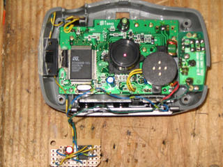
While shopping at Wal-Mart the other day, I came across a little digital camera that was advertised as being "keychain-sized". The resolution and number of pictures is equivalent to what the camera I used in this project but it is about an eighth the size and uses only one AAA battery instead of three. Using this for kite-based photography would allow for flights in lower wind speeds. There a couple of issues that I can think of with using this camera instead of the larger one. The first is that the power on-board the camera would only be 1.5v instead of 4.5v, so you would need another source of power for the 555 timer, perhaps two 3v lithium watch batteries. The other concern I would have is that it might be too light and get tossed around more easily in the wind, but I'm sure there's a way that this could be alleviated.

I've looked around on Wal-Mart's website, but I can't find the camera that I saw, but here's a similar one that I found on another site.

Saturday, October 22, 2005

Another Site with Good Circuits

Here's another good site with some interesting circuits and even some board layouts for etching your own (I've yet to post that tutorial - that will be coming soon - promise!). The circuits are categorized into light & LASER, sound & radio, power supply, auto, computer, and phone circuits. There are quite a few that look to be really interesting and useful; I'm considering making the automatic headlight dimmer, for example. Looks to be a good resource for finding intersting circuits to build and he even gives some advice on another page for where to get parts.

Monday, October 17, 2005

Chip Directory - A Handy Resource

Here's a handy resource that I found - a chip directory that lets you search for information about just about any integrated circuit you might come across. This would be very useful for finding out pinouts, looking up manufacturers, or discovering exactly what that weird chip does that a particular circuit calls for. Having played around with it for a little while, it looks to be pretty good if a little weird at times, but all-in-all seems to be a pretty good resource that's worth bookmarking.

Timed Digi-Cam


Here’s a little project that I found a while back when looking for a way to take aerial photographs from a kite. I needed a way to trigger the shutter for the camera for the ground, and had toyed with the idea of some sort of radio-based triggering, but decided to go with a simple timer. The circuit connects to a simple, low-resolution digital camera (which is not the Stylecam mentioned in the article, but similar enough to work) that I got for Christmas a few years ago. I soldered directly on to a few points of the camera - +5, ground, and one side of the push-button that operates the shutter. The heart of the circuit is the classic 555 timer which sends a pulse out roughly once every five seconds that lasts long enough to simulate pressing the push-button. With the capacity of the camera limited to 20 pictures, this lasts for a little over a minute and a half – usually long enough to get the camera and kite up to a decent height for interesting pictures.

Saturday, October 15, 2005

Simple Project: SNES RF-Adapter

Here’s a simple little project that came out of necessity – I had an extra Super Nintendo that I wanted to give to my girlfriend, but none of the accessories for it – controllers, AC adapter, and… an RF-adapter to connect it to a TV. Long story short, I got everything else except the adapter and didn’t want to have to pay big bucks to get a “real” adapter from eBay or used from a used-game place. I decided that it couldn’t be terribly difficult to make, and that this could be an interesting little project.

My first step was to open the existing adapter from my Super to see what makes it tick. It turns out that there really isn’t too much to it, just some circuitry to handle the automatic switching of the signal from the antenna or from the Super. Since this didn’t really work very well to begin with (the picture from the antenna was often fuzzy), I decided to not try to copy this circuit, but instead to use an RF switch I had lying around from a previous cable-TV installation. I soldered and heat-shrunk the cable from an RCA-style plug onto one of the inputs of the switch and left the other side open for connection to an antenna.

That’s it for construction – just a few cables in the right spots and it works like a charm. This just goes to show that not all projects have to be difficult to be useful!

Thursday, October 13, 2005

Live Site Post

"Hidden" Lab on Campus

There are many labs around campus, but I one that often has some empty machines that I don't think is as well-known as say, the one in the basement of Northside Hall or the multitude that are available in Darwin and Wiekamp Hall is the one that is to the left of the circulation desk in Schurz Library. It is sort of tucked away and therefore not as visible as the others, but the signs are there for it. There are about 20 PCs and Macs available, with a printer and some scanners as well. It does get full sometimes, but often times it's not too hard to find a free machine.

Wednesday, October 12, 2005

Wikipedia Topic

I have definitely decided that I will do my Wikipedia topic on my employer, Tenneco Automotive. Right now, I don't know a whole lot about the history of the company, other than it has been around for quite some time. I know that Tenneco owns the brands Monroe, Walker, Clevite, Gillet, Ranch, DynoMax, Fonos, Fric-Rot, Kinetic, Thrush, and DNX. Whew! Also - according to the site, we have "74 manufacturing facilities located in 22 countries and on 6 continents". The company has been publicly traded on the NYSE since November 5, 1999 under the symbol TEN and is a $3.5 billion company with 19,600 employees. I will try to find out some more information about the company on Friday when I can pick the brains of some of the folks who have been around for a little while...

Tuesday, October 11, 2005

Schematics Galore!

Once you have your bench set up check out this site for all sorts of schematics for a variety of different circuits - from Alarms to Video projects and everything in between. Not all of the links work so you'll have to kind of poke around for a good one, but there are usually multiple links to similar projects.

Monday, October 10, 2005

The Well-Stocked Bench (Mark II)

Yesterday I mentioned some of the essentials for a well-stocked electronics bench. Poking around a bit, I've found a nice write-up by Andrew Walmsley and edited by Rod Elliott which goes into a lot more depth than my little post and further discusses how to use some of the equipment they suggest. He also lists some cautions when working with electricity that you would be wise to follow! Definitely worth a look for those considering embarking on this strange and wonderful hobby...

Drive Safely With Your Cell Phone


Or: "Avoid that Crick in the Elbow from Long Conversations While Driving"...

So I realized that when I talk on my cell phone and drive (tsk tsk, I know) I do tend to get a sore elbow after a while, and also I have a tendency to lean with said elbow on the armrest causing me to tilt my head which probably isn't a good driving practice. To top all of this off, if I'm holding the cell phone, that hand is not available to do other things like hold the wheel, adjust mirrors, play with the radio, and... um... eat breakfast. Not that I'd ever do that. So - I thought about this, and have seen some of those gadgets on TV that promise to pipe your cell audio through your stereo via a doofy-looking FM transmitter that plugs into your cigarette lighter. These, in addition to looking doofy, are more than I want to pay for what they provide. I decided that since I already have an adapter to run audio from a headphone jack into my tape deck and since I have a microphone from a headset that I never use that I would make a little plug that would send the audio from the microphone into the cellphone and the output from the cellphone into a headphone jack. To do all of this I stopped at Radio Shack after work and bought a 3/32" stereo plug with solderable contacts and a pair (that's how the packages come... I've now got a spare for another day!) of 1/8" stereo headphone jacks. I then took apart the headset I already had and determined which wires go where with my multimeter. The "sleeve" of the jack (the part closest to the wires) is ground for both the microphone and the speaker. The center goes to the other side of the speaker and the tip goes to the other side of the microphone. I then soldered the microphone to the connections for ground and tip and the headphone socket to the connections for ground and middle. This accomplished, I tried it out by clipping the microphone to my visor and plugging the input to my tape adapter into the headphone jack and dialing a number using voice-dial on the phone. First time - worked like a charm! It's kind of cool really to hear the cell audio going through the car stereo and being able to dial and talk without taking my hands off of the wheel except to answer and press and hold the voice-dial button.

I'll add pictures later - currently on a lousy dial-up connection...
Picture added - I have no macro lens for my camera, so the "in progress" ones look terrible

Sunday, October 09, 2005

Interesting Electronics-Related Site

Surfing around, I found the homepage for "The Under the Pier Show", that is, to quote the site's author "A MAD COLLECTION OF HOME-MADE SLOT MACHINES & SIMULATOR RIDES ON SOUTHWOLD PIER, SUFFOLK, UK". This really is the best description for what all he has built for his venue. The machines are all hand-made and incredibly well-done. The ideas that he has come up with and implemented are very interesting and well thought-out. If you have a few minutes, I would suggest poking around for a while. The site is not the best-organized in the world, and some projects are not available from the main page, but clicking the various links throughout the other descriptions should get to the pages for most of his projects - it's definitely worth looking around!

The Well-Stocked Bench

As a continuation on my previous post about where to buy components, I thought that I would write a piece about what should be on a bench for those looking to start building fun and exciting circuits.

First - equipment. A good multimeter is a must for testing and diagnosing circuits (believe me - this is where a lot of time is spent!). I would suggest getting a digital, autoranging multimeter for the convenience that both offer - digital since it's easy to read and reasonably foolproof and autoranging so that you don't have to worry about what the voltage/amperage levels are before you put the meter on. A multimeter should be able to measure resistance, amperage, continuity, and voltage at the least and some of the better ones can measure capacitance and other useful things. For digital circuits, a logic probe is handy for showing digital levels when testing and can be bought or fairly easily built.
When constructing a circuit, a soldering iron is a must - my current setup is a generic 35-watt pencil type iron with a 15-watt tip from Radio Shack. The mismatch in wattages is intentional - I like the heat output from a 35-watt iron, but I like the fine tip that comes with the lower wattage tips. This is not dangerous to do - the tip is just a piece of pointy metal. I have found that when it comes to solder, a 60/40 lead/tin solder in the smallest diameter you can find is quite good for most applications. Along with the soldering iron, I would suggest getting a desoldering iron. As its name would imply, this is similar to a soldering iron, except that the tip is hollow and connected to a rubber squeeze-bulb to remove solder from a board. This can have dual-applications - one for fixing mistakes and the other for the removal of components from existing circuit boards, which can be a great way to get parts cheap!
Good lighting is a huge help when working on tricky circuits, especially ones with many small components in them. A setup with two standard fluorescent light fixtures spaced a couple of feet apart overhead will help to eliminate shadows and provide clean, even white light to the bench.

For components - the more the merrier, really! A good collection of resistors in various resistances as well as a good stock of film and electrolytic capacitors is almost always useful - there are many times when a circuit will require some odd resistance or capacitance and it's nice to have all of these handy. They are cheap enough to stock up on without breaking the bank and will most likely show up in one form or another in most circuits. LEDs and standard diodes are also good to keep a decent stock of - again they are fairly cheap, and many circuits will use them - LEDs are especially useful for diagnosing digital circuits or for building into them to show logic levels at key points. For the digital enthusiast, a must-have in nearly any circuit is the LM7805 5 volt voltage regulator. This will take input from a power supply ranging from ~6v to ~35v and convert it to 5 volts - the standard logical high level used by most chips. Caution on these - they do tend to get hot when they're running, especially when input is toward the high-end, so you might want to stick a heatsink on it. Common digital ICs will include the 7400 NAND gate, 7402 NOR gate, 7404 hex inverter, 7408 AND gate, 7432 OR gate, 7486 XOR gate, 7474 D flip-flop, and 7486 J-K flip-flop for a good starting point. Datasheets for all of these can be found through this site.

For prototyping circuits, a breadboard is a good way to play around without setting anything into stone (or solder as the case may be...). Once a circuit is tested and working, it can be made more permanent by moving it over to a electroncis perfboard. This is similar to the breadboard in layout, but is made of formica and has copper cladding on the back to solder to. For making a lot of circuits, or for making a nice-looking board, etching is the way to go. More on this in a later post, as there are many ways to do this...

8x16 LED Matrix


Here's a project that I'm dusting off from a couple of years ago - a homemade 8x16 LED matrix. Basically this is a small version of the type of sign often used for displaying messages along the sides of roads, in stores, etc... The resolution is not great and it's not really wide enough to be totally practical, but it is a good proof of concept and an excellent way to hone the 'ol soldering skills.

The device is really quite simple from the hardware point of view - it consists of 128 LEDs that are arranged into a matrix of sixteen columns and eight rows. The cathodes of all of the LEDs in a column are all tied together and are only grounded when the circuit is completed by a transistor. Similarly, the anodes of all of the LEDs in a row are tied together and are only supplied current when completed by a transistor. The transistors grounding the columns receive their signals from a 74LS154 demultiplexer that has four digital inputs and sixteen digital outputs. The signals must first pass through a 4069 hex inverter since the output from the demux is opposite of what we want (selected output is low, others are high which is not what we want). Only one column can be grounded at any given time. The input to the demux comes from four of the output pins of a PC parallel port. The rows are driven using the other eight output lines from the parallel port so that any combination of rows can be high at any one time.

This is it for the hardware - everything else is done in software. For this project I have written the test software in Microsoft QuickBASIC 4.5 but have ported the code to C++ so that it can run well on most architectures. Because only one column is grounded at any given time, I had to rely on persistence-of-vision to make it appear that all columns are lit when needed. This is accomplished by looping through all of the columns very rapidly and setting the output on the rows as necessary when the proper column is grounded. This results in a fairly smooth looking picture without too much flicker. The most common application for this sort of sign was the first program that I wrote for it - displaying a scrolling message. Due to the limits on the width (approximately 2.5 characters) scrolling is required to display all but the shortest messages. The software for this is quite simple - just an array to hold all of the row values (I developed a simple font that converts characters to the correct row values) that gets output to the display. When it comes time to scroll, simply rotate the array so that position 1 of the array corresponds with the first column on the display.

Sourcecode (QB)

Schematic - I cannot find the schematic that I based mine on that I was going to post here, and I haven't yet drawn one for what I built - I'll try to make this link useful soon...

Saturday, October 01, 2005

Put Your Electronics Knowledge to Use: Become a Ham!

Sorry if this sounds a little "sales"ish...

One good way to put electronics knowledge and love to use is to become an amateur radio operator (ham)! This is a very interesting field that allows you to talk to people the world over, assist in emergencies, send pictures, and much much more. This is considerably different from just using a CB radio to talk to people - first, a license from the FCC is required so not just anyone can get on - also, the number of available frequencies and the power allowed on each are consierably greater than anything available without a license.

The best way to get started would be to take some practice tests, read some books, and find a local test time and location. The cost of taking the exam is typically less than $15 and there are only 35 questions, so it shouldn't take more than half an hour.